| www.tmatlantic.com
Test & Soldering Equipment On-line Store |
|
D.E.V.I.C.E. (Wiki)Calculators Services |
|||||
Filter by first letter
|
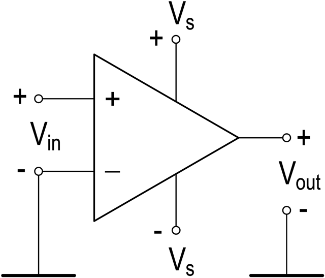
Operational amplifierAn operational amplifier (op-amp) is an electronic amplifier of direct current, with a differential input and usually one output. Such an amplifier has a very high gain. HistoryThe operational amplifier was originally developed in the 1930s. The operational amplifier was designed to perform mathematical operations (hence the name - operational amplifier) as part of the first analog electronic computers (with mathematical operations - addition, subtraction, integration, differentiation, etc.) In the 60s an American Fairchild Semiconductor company developed the world's first op-amp in the form of a microcircuit. Operating principleThe differential input (from the Latin differentia - "difference") of the device consists of a non-inverting (Vin+) and inverting (Vin-) inputs. See Fig. 1.
An ideal op-amp amplifies the difference in voltage at the inputs of the operational amplifier, while the common-mode signal (that is, coinciding in magnitude and phase at both inputs) does not affect the resulting voltage. To calculate the output voltage Vout at the output of an ideal operational amplifier (without feedback), the formula is used: Vout = G Ч (Vin1 − Vin2) where:
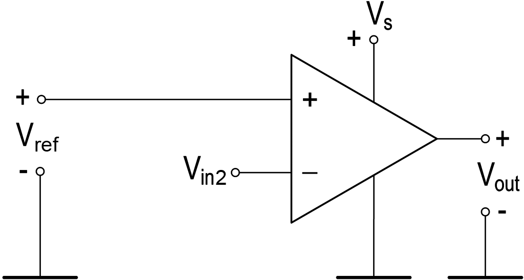
In practice, such a circuit (without feedback) is not used, with the exception of the comparator circuit. Most commonly used in 741 and LM308 chips. Comparison of parameters of ideal and real operational amplifier
In engineering calculations, the gain of an ideal operational amplifier (G) is usually taken to be infinity. We will take a real operational amplifier - LM358. Its gain is approximately 100,000. Using the formula above, we calculate the output voltage (Vout) of the operational amplifier for two cases.
In practice, the output voltage of the operational amplifier naturally cannot exceed the supply voltage. Thus, the output voltage of the operational amplifier in these cases will be equal to its positive (+Vsat) or negative (-Vsat) saturation voltage. Most operational amplifiers, including the LM358 considered in the example, have positive and negative saturation voltages with a single-polar supply equal to Vs – (1...2) and 0 Volts, respectively, where Vs is the supply voltage. Operational amplifiers are manufactured whose output saturation voltage is practically equal to the supply voltage (the so-called "rail-to-rail" amplifiers). It should also be taken into account that the amplifier's output voltage is affected by the load resistance. A low-resistance load at the amplifier's output will reduce its output voltage.
Typical circuits for using an operational amplifier are:
Use our online Operational Amplifier Gain Calculator. |
Measurement History Events
|
Site mapPrivacy policyTerms of Use & Store PoliciesHow to BuyShippingPayment


|


