| www.tmatlantic.com
Test & Soldering Equipment On-line Store |
D.E.V.I.C.E. (Wiki)Calculators Services |
||||||
Filter by first letter
|
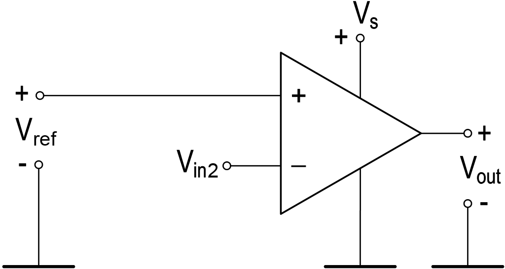
ComparatorA comparator (from the Latin comparare "to compare") is the simplest circuit for connecting an op amp. The operating principle is to compare the input voltages and output a constant voltage at the amplifier output V+, if V1 > V2, or V-, if V1 < V2. The comparator circuit is shown in Fig. 1.
A comparator is used in electronic circuits (for example, to compare readings from two sensors) and is used as the main element of an analog-to-digital converter (ADC) when comparing the values of the input voltage and the generated value based on a digital code (for a successive approximation ADC).
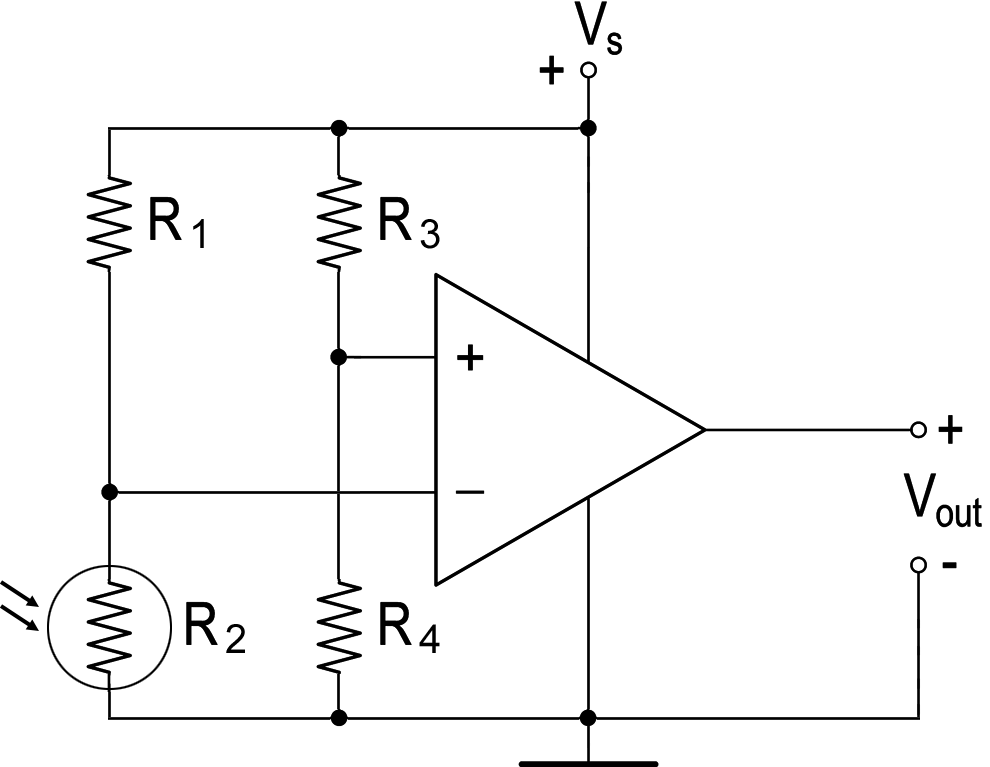
The comparator is convenient for processing signals from analog sensors and converting them into a discrete form. For example, a simple light sensor can be built on the comparator (Fig. 3).
Resistors R1-R4 form the so-called bridge circuit. R1 and R2 are one part of the bridge, and R3 and R4 are the other. This circuit is the most typical when connecting sensors. The comparator in this circuit detects the potential difference in both halves of the bridge. The comparator circuit shown in Fig. 2 has a significant defect in practice. When a real (noisy) signal from an analog sensor is fed to the comparator input, multiple switching of the output voltage (Vout) will be observed at the output (Fig. 4). Fig. 4. It is not recommended to use such an output signal for control. To correct the signal waveform in such cases, an operational amplifier based comparator with positive feedback (Schmitt trigger) is used. |


|