| www.tmatlantic.com
Test & Soldering Equipment On-line Store |
|
D.E.V.I.C.E. (Wiki)Calculators Services |
|||||
Filter by first letter
|
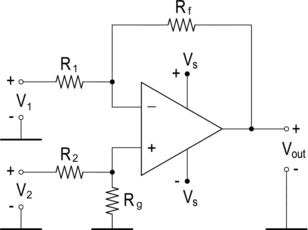
Differential amplifierThe circuit diagram of the differential amplifier based on the operational amplifier is shown in Fig. 1.
A differential amplifier based on the operational amplifier is an electronic amplifier with an output voltage Vout equal to the difference between V1 and V2, multiplied by a constant:
To suppress the common-mode component, i.e. amplification of only the difference between V1 and V2, it is necessary to observe the ratio of the resistors' resistances: R1 / Rf = R2 / Rg With this ratio, the gain of the common-mode component will be equal to zero, and Vout will depend only on the difference between V1 and V2: Vout = Rf / R1 × (V2 – V1) A differential amplifier is used in signal circuits in which useful information is carried not by a specific voltage value relative to a common conductor, but by the voltage difference between two signal lines. The simplest example is a current sensor in multimeters or power supplies. In these circuits, the potential difference between the terminals of a low-resistance resistor connected in series with the load and used as a current sensor.
Digital technology interfaces (Ethernet, CAN, USB, HDMI, and others) are implemented using a differential circuit. In it, information is transmitted over pairs of wires. Common mode noise, perceived at the output of the communication line, affects both conductors in a pair equally and is easily suppressed in the input differential amplifier. Use our online Op Amp Differential Amplifier Calculator |
Measurement History Events
|
Site mapPrivacy policyTerms of Use & Store PoliciesHow to BuyShippingPayment


|


