| www.tmatlantic.com
Test & Soldering Equipment On-line Store |
D.E.V.I.C.E. (Wiki)Calculators Services |
||||||
Filter by first letter
|
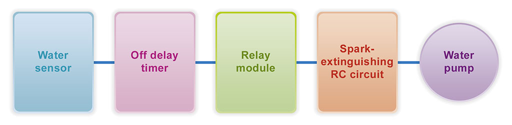
Designing Off Delay Timer Switch for Water PumpThis article is about equipment protection from water. We have a powerful pump that quickly removes incoming water. High removal speed is crucial because water influx varies, and we need to handle maximum flow. If the flow is low, the water will be removed quickly, and the motor will shut off. Rapid motor shutdown within 1-3 seconds after starting is not ideal. The motor should remain on for at least 10 seconds. At the beginning of any design process, it is necessary to break the project down into simple sections (parts) depending on their functions within the overall project. The result of this design phase is a so-called functional diagram or block diagram. In an off delay timer project, four functional blocks can be clearly identified: sensor, timer, relay, and motor. Since the motor is an inductive load, relay contacts require protectionthis is provided by an arc-suppressing RC circuit. Thus, we have 5 blocks (Fig 1).
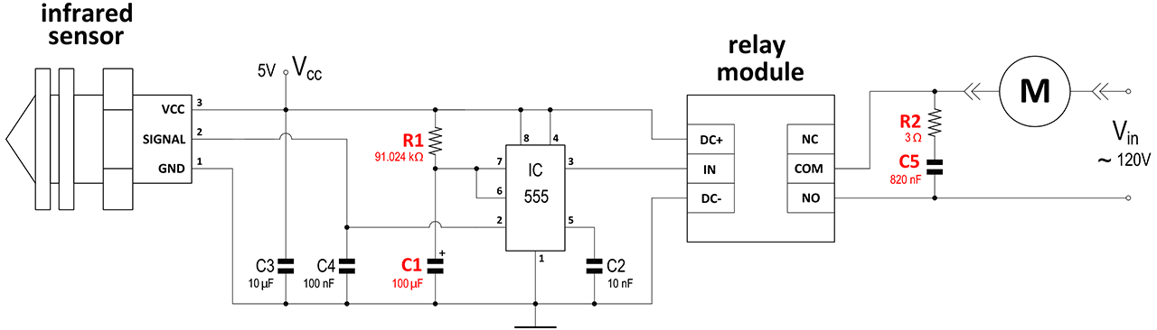
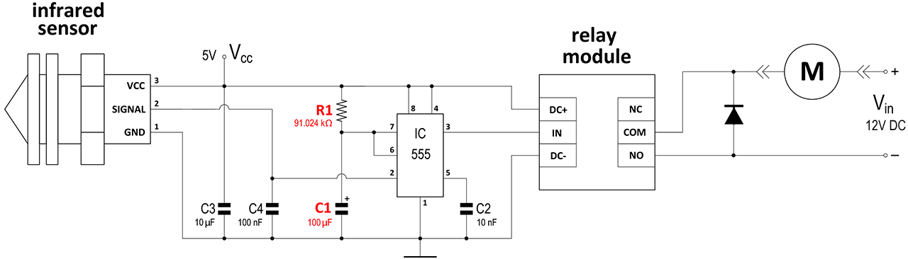
Next, during the design process, it is necessary to study the characteristics of each block, each part. For ready-made partssuch as sensors or motorsit is sufficient to study the label or user manual from the manufacturer. If these are not available or unclear, the part must be tested. For example, for an optical water sensor, you need to determine the actual output signal levels (as shown in the video here or see below). The next step in the design is to choose the timer circuit option. There may be several timer variants (using a single transistor, TTL elements, or IC 555). In this project, a typical off delay timer circuit using a Square Wave Generator with an IC 555 in monostable mode is employed. The circuit itself and its calculator for the Square Wave Generator with IC 555 in monostable mode are available on the website, which significantly speeds up and simplifies the design process.
Designing Off Delay Timer Switch for Water Pump ControlFrequently Asked Questions
|


|